Data Transmission Media
1. Guided Media
2. Unguided Media
1.
Guided Media:–
Guided Media:–
I.
Twisted Pair
II.
Coaxial Cable
III.
Optical Fiber
I.
Twisted Pair:- A twisted pair wire consists of two
bunches of thin copper wires, each bunch enclosed separately in plastic
insulation, then twisted around each other to reduce interference by adjacent
wires. It is also called UTP (Unshielded Twisted Pair) cable, because other
than the plastic coating around the two individual bundles of copper wires,
nothing shields it from outside interference.
UTP
cables are commonly used in local telephone communication and short distance (up
to 1 KM) digital data transmission. Data transmission is up to 9600 bps (bits
per second/9600 baud).
cables are commonly used in local telephone communication and short distance (up
to 1 KM) digital data transmission. Data transmission is up to 9600 bps (bits
per second/9600 baud).
UTP cables are a less expensive medium, they are
easy to install and use. They pick up noise easily, that’s why their use is limited and they also cause high error rates.
easy to install and use. They pick up noise easily, that’s why their use is limited and they also cause high error rates.
II.
Coaxial Cable: – Coaxial cables are groups of
specially wrapped and insulated wire lines that are able to transmit data at high speed.
Coaxial Cable: – Coaxial cables are groups of
specially wrapped and insulated wire lines that are able to transmit data at high speed.
There is a central copper wire
covered with PVC insulation. And another sleeve of copper mesh is placed over the PVC insulation.
The metal sleeve is also covered by an outer shield of thick material that is made of PVC.
The signal is transmitted by the inside copper wire that is electrically shielded by the outer metallic sleeve.
We find a huge amount of bandwidth on Coaxial cables than the UTP cables. These are
capable of transmitting digital signals at rates of 10 Mbps. They are used in
long-distance telephone lines and as a cable for cable T.V.
capable of transmitting digital signals at rates of 10 Mbps. They are used in
long-distance telephone lines and as a cable for cable T.V.
Coaxial cables have much higher noise immunity; it is suitable for data
transmission without distortion or loss of signal.
III.
Optical Fibers:- Optical fibres are hair-thin threads
of glass or plastic. It can carry light signals instead of electrical signals.
Light can travel much faster than electricity. So OFCs can transmit data at a much
higher speed than copper wires or coaxial cables over very long distances.
Optical Fibers:- Optical fibres are hair-thin threads
of glass or plastic. It can carry light signals instead of electrical signals.
Light can travel much faster than electricity. So OFCs can transmit data at a much
higher speed than copper wires or coaxial cables over very long distances.
A Fiber Optic Cable consists of three
concentrated layers – The inner port which carries the light signals, a
cladding around it, which keeps the light in the core and the outer protective
coating, which protects the cladding.
concentrated layers – The inner port which carries the light signals, a
cladding around it, which keeps the light in the core and the outer protective
coating, which protects the cladding.
The inner core has a diameter of 8-200 micrometres, consists of a bunch
of optical fibres.
The cladding is made up of plastic or glass and has a refractive index.
The outer protective layer is made up of plastic.
Ø Advantages:-
Large Bandwidth–
Optical fibres can have the bandwidth in the range of 200 MHz(MegaHertz) per KM to
3.00 GHz(Gigahertz) per KM.
Optical fibres can have the bandwidth in the range of 200 MHz(MegaHertz) per KM to
3.00 GHz(Gigahertz) per KM.
Low loss- if we compare light signals with electrical signals, then light signals can travel at very high speed. And there will be almost no loss over long distances.
Immunity to
electromagnetic interference:– Optical fibre transmissions are not affected
by magnetic or electrical interference.
electromagnetic interference:– Optical fibre transmissions are not affected
by magnetic or electrical interference.
Small size and lightweight:– Optical Fiber Cables with a core and cladding of 0.125 micro-meter
diameters and 3.5 micro-meter outer protective coatings has the capacity to carry
signals 100 times more than 900 twisted pair copper wires.
diameters and 3.5 micro-meter outer protective coatings has the capacity to carry
signals 100 times more than 900 twisted pair copper wires.
Security:– Optical
fibres offer increased security against unauthorized tampering of information since it is extremely difficult and expensive to tap optical signals.
fibres offer increased security against unauthorized tampering of information since it is extremely difficult and expensive to tap optical signals.
Safety and electrical
insulation:– Optical fibres being insulators provide no electrical spark
hazards and be safely used. It can carry both analogue and digital signals.
insulation:– Optical fibres being insulators provide no electrical spark
hazards and be safely used. It can carry both analogue and digital signals.
Ø Disadvantages:-
1). Optical fibres
being fragile can’t be easily turned at sharp corners.
being fragile can’t be easily turned at sharp corners.
2). Aligning and
joining two fibre optic cables is not easy.
joining two fibre optic cables is not easy.
TYPES OF OPTICAL FIBERS
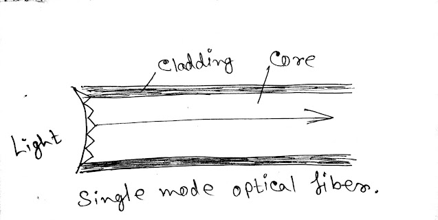
a). Single-mode optical fibre.
b). Multi-mode optical fibre.
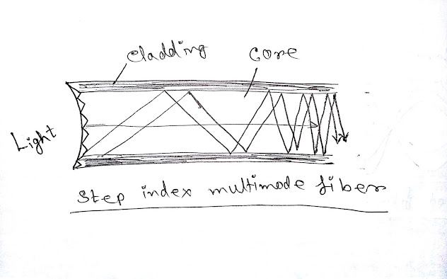
c). Step index multimode fibre.
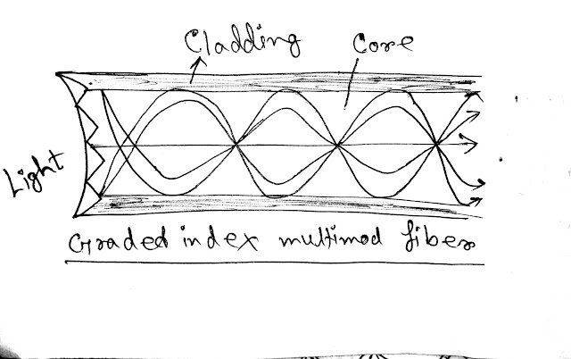
d). Graded index multimode fibre.
a). Single-mode optical fibre:– Single-mode optical fibre has a small
diametric core that allows only one mode of light to propagate. for this reason, the number of light reflections created as the light passes through the
core decreases, lowering attenuation and creating the ability for the signal to
travel faster, further. This is used for long distances transmission.
b). Multi-mode optical fibre:– This cable has a large diametric core
that allows multiple modes of light to propagate. for this reason, the number of light reflections created as the light passes through the core increases creating the ability of more data to pass through at a given time. As soon as we increase the distance, the quality of the signal will reduce.
that allows multiple modes of light to propagate. for this reason, the number of light reflections created as the light passes through the core increases creating the ability of more data to pass through at a given time. As soon as we increase the distance, the quality of the signal will reduce.
This is used for short-distance
data, audio, video, application, LANs. Radiofrequency broadband cannot be
transmitted.
data, audio, video, application, LANs. Radiofrequency broadband cannot be
transmitted.
c). Step index multimode fibre:– Due to its large core, some of the
light rays may travel a direct route, whereas others are zigzag as the bounds of
the cladding. For this reason, at the receiving point different group of light rays arrives differently. This is suitable for short distances.
light rays may travel a direct route, whereas others are zigzag as the bounds of
the cladding. For this reason, at the receiving point different group of light rays arrives differently. This is suitable for short distances.
d). Graded index multimode fibre:– This fibre contents a core in which
the refractive index diminishes gradually from the centre access out towards
the cladding. There is a higher refractive index at the centre that moves down the access more slowly than near the cladding. Due to
the graded index, light in the core curves helically rather than zigzag of the
cladding its travel distance. It offers less dispersion and is suited for LANs.
2). Unguided Media:–
I. Radio Waves
II. Microwaves— *Terrestrial microwaves
*Satellite
III. Infrared
I.
Radio waves:– Electromagnetic waves ranging in
frequencies between 3KHz(Kilo Hertz) and 1GHz are normally called radio waves.
Radio waves are Omi-directional. When the antenna transmits radio waves, they are
propagated in all directions. This reflects that the sending and receiving
antennas should not have to be aligned.
Microwaves:– Electromagnetic waves having frequencies between 1 GHz and 300 GHz are called
microwaves.
microwaves.
(*). Terrestrial Microwaves:– It uses directional parabolic
antennas to send and receive signals in the lower GHz ranges. The signal is highly focused and the physical path has to be a line of sight. Repeaters are used to extend signals the system is used whenever
cabling is cost-prohibitive, such as hilly areas or crossing rivers.
antennas to send and receive signals in the lower GHz ranges. The signal is highly focused and the physical path has to be a line of sight. Repeaters are used to extend signals the system is used whenever
cabling is cost-prohibitive, such as hilly areas or crossing rivers.
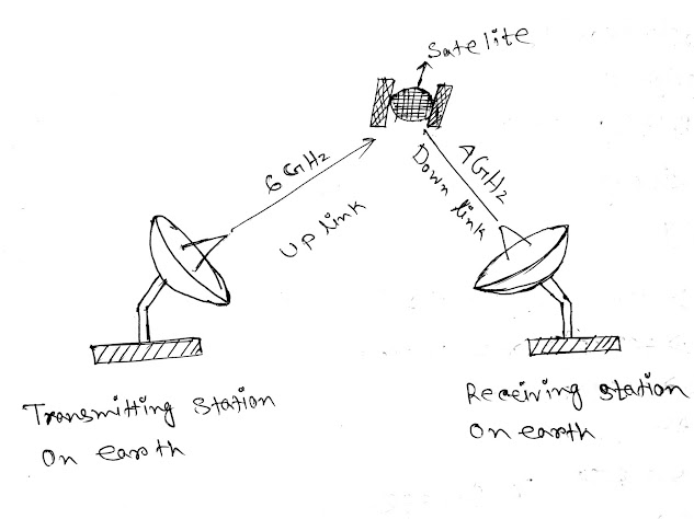
(*). Satellite:- A
communication satellite is basically a microwave relay station placed at 36000
km above the Equator where its orbit speed exactly matches the earth’s
rotation speed. Since a satellite is positioned in a geosynchronous orbit, it
appears to be stationary relative, to earth and always stays over the same
point with respect to earth. This allows a brown station to aim its antenna
and a fixed point in the sky.
VSAT
(VERY SMALL APERTURE TERMINAL)
Smaller dish antennas having a low power
transmitter and receiver have been built for installation at the user’s
sites. These dish antenna systems are
known as VSATs. The Diameter of the dish antenna is called aperture, which is about 1 to 2 meters.
transmitter and receiver have been built for installation at the user’s
sites. These dish antenna systems are
known as VSATs. The Diameter of the dish antenna is called aperture, which is about 1 to 2 meters.
(*) Infrared (IR):– Infrared signals with frequencies
from 300 GHz to 400 THz( TeraHertz) can be used for a short distance transmission or communication.
from 300 GHz to 400 THz( TeraHertz) can be used for a short distance transmission or communication.
Infrared
signals having high frequencies can’t penetrate walls. These adventitious
features prevent interference between one system and another.
signals having high frequencies can’t penetrate walls. These adventitious
features prevent interference between one system and another.
Infrared
applications include communication between devices such as keyboards, mice, P.C., Printers.
applications include communication between devices such as keyboards, mice, P.C., Printers.
(*) Signal Propagation Unguided Media:–
1). Ground wave propagation
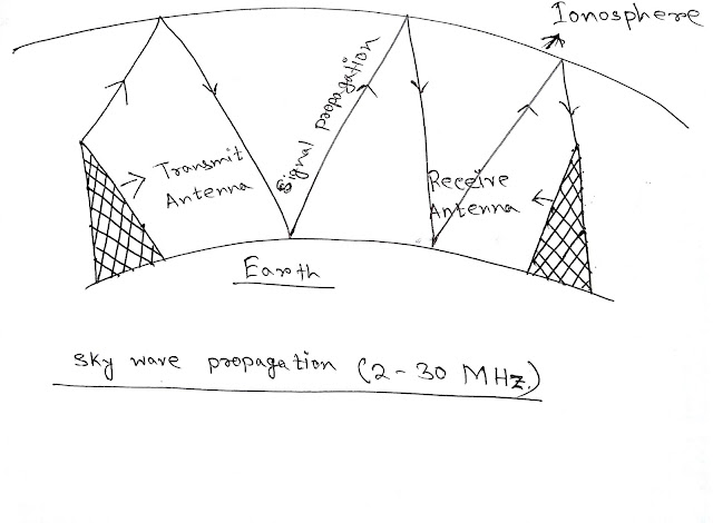
2). Skywave propagation
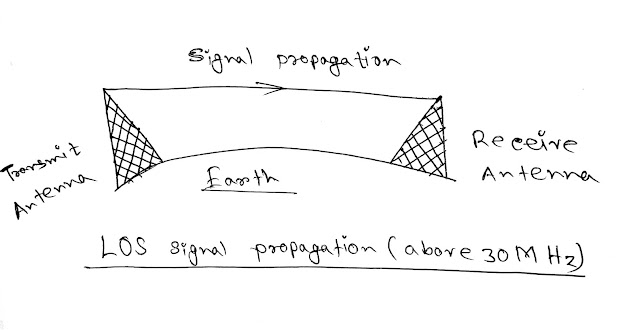
3). Line-of-sight(LOS)
1). Ground wave propagation:– Inground wave propagation, radio
waves travel through the lowest portion of the atmosphere. Their low-frequency
signals originate in all directions from the antenna and follow the curvature
of the earth.
waves travel through the lowest portion of the atmosphere. Their low-frequency
signals originate in all directions from the antenna and follow the curvature
of the earth.
2). Skywave propagation:– Higher frequency radio waves travel
upward into the atmosphere where they are reflected back to the earth. This
allows greater distances.
upward into the atmosphere where they are reflected back to the earth. This
allows greater distances.
3). Line of sight:– In the line of sight very high-frequency
signals are transmitted in straight
lines directly from antenna to antenna. The antenna must be directional facing to close
enough together.
signals are transmitted in straight
lines directly from antenna to antenna. The antenna must be directional facing to close
enough together.



I admire this article for the well-researched content and excellent wording. I got so involved in this material that I couldn’t stop reading. I am impressed with your work and skill. Thank you so much. Single Mode Fiber Connectors
Nice article, which you have shared here. Your article is very informative and I liked your way to express your views in this post. Thanks for sharing this article here. Single Mode Fiber Connectors.